How to Draw a Line on a Png Matlab
Plot line transparency and color gradient
In the past few weeks, I discussed the new HG2 axes Backdrop and Baseline properties with their associated ability to specify the transparency level using a fourth (undocumented) element in their Color.
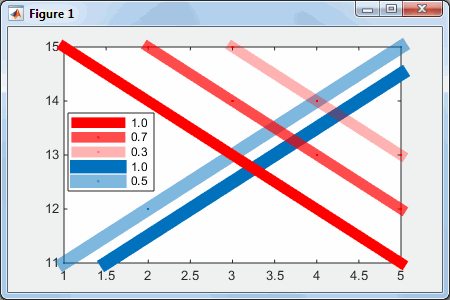
In other words, color in HG2 can still be specified as an RGB triplet (e.g., [1,0,0] to symbolize bright red), but also via a 4-element quadruplet RGBA, where the 4th element (Alpha) signifies the opacity level (0.0=fully transparent, 0.5=semi-transparent, 1.0=opaque). So, for example, [1, 0, 0, 0.3] means a 70%-transparent red.
This Alpha element is not documented anywhere as being acceptable, but appears to be supported almost universally in HG2 wherever a color element can be specified. In some rare cases (e.g., for patch objects) Matlab has separate Alpha properties that are fully documented, but in any case nowhere have I seen documented that we can directly set the alpha value in the color property, especially for objects (such as plot lines) that do not officially support transparency. If anyone finds a documented reference anywhere, please let me know – perhaps I simply missed it.
Here is a simple visualization:
xlim ( [ 1,5 ] ); hold ( 'on' ); h1a = plot ( 1:5, 11:15, '.-', 'LineWidth',10, 'DisplayName',' 0.5' ); h1b = plot ( 1.5:5.5, 11:15, '.-', 'LineWidth',10, 'DisplayName',' 1.0', 'Color',h1a.Color ); % 100% opaque h1a.Color ( 4 ) = 0.5; % 50% transparent h2a = plot ( 3:7, 15:-1:11, '.-r', 'LineWidth',8, 'DisplayName',' 0.3' ); h2a.Color ( 4 )=0.3; % 70% transparent h2b = plot ( 2:6, 15:-1:11, '.-r', 'LineWidth',8, 'DisplayName',' 0.7' ); h2b.Color ( 4 )=0.7; % 30% transparent h2c = plot ( 1:5, 15:-1:11, '.-r', 'LineWidth',8, 'DisplayName',' 1.0' ); % 100% opaque = 0% transparent legend ( 'show','Location','west' )
xlim([1,5]); hold('on'); h1a = plot(1:5, 11:15, '.-', 'LineWidth',10, 'DisplayName',' 0.5'); h1b = plot(1.5:5.5, 11:15, '.-', 'LineWidth',10, 'DisplayName',' 1.0', 'Color',h1a.Color); % 100% opaque h1a.Color(4) = 0.5; % 50% transparent h2a = plot(3:7, 15:-1:11, '.-r', 'LineWidth',8, 'DisplayName',' 0.3'); h2a.Color(4)=0.3; % 70% transparent h2b = plot(2:6, 15:-1:11, '.-r', 'LineWidth',8, 'DisplayName',' 0.7'); h2b.Color(4)=0.7; % 30% transparent h2c = plot(1:5, 15:-1:11, '.-r', 'LineWidth',8, 'DisplayName',' 1.0'); % 100% opaque = 0% transparent legend('show','Location','west')

Now for the fun part: we can make color-transition (gradient) effects along the line, using its hidden Edge property:
>> h2b.Edge.get AlignVertexCenters: 'off' AmbientStrength: 0.3 ColorBinding: 'object' ColorData: [4x1 uint8 ] ColorType: 'truecoloralpha' DiffuseStrength: 0.6 HandleVisibility: 'off' HitTest: 'off' Layer: 'middle' LineStyle: 'solid' LineWidth: 8 NormalBinding: 'none' NormalData: [ ] Parent: [1x1 Line ] PickableParts: 'visible' SpecularColorReflectance: 1 SpecularExponent: 10 SpecularStrength: 0.9 StripData: [ 1 6 ] Texture: [ ] VertexData: [3x5 single ] VertexIndices: [ ] Visible: 'on' WideLineRenderingHint: 'software' >> h2b.Edge.ColorData %[4x1 uint8] ans = 255 0 0 179
>> h2b.Edge.get AlignVertexCenters: 'off' AmbientStrength: 0.3 ColorBinding: 'object' ColorData: [4x1 uint8] ColorType: 'truecoloralpha' DiffuseStrength: 0.6 HandleVisibility: 'off' HitTest: 'off' Layer: 'middle' LineStyle: 'solid' LineWidth: 8 NormalBinding: 'none' NormalData: [] Parent: [1x1 Line] PickableParts: 'visible' SpecularColorReflectance: 1 SpecularExponent: 10 SpecularStrength: 0.9 StripData: [1 6] Texture: [] VertexData: [3x5 single] VertexIndices: [] Visible: 'on' WideLineRenderingHint: 'software' >> h2b.Edge.ColorData %[4x1 uint8] ans = 255 0 0 179
The tricky part is to change the Edge.ColorBinding value from its default value of 'object' to 'interpolated' (there are also 'discrete' and 'none'). Then we can modify Edge.ColorData from being a 4×1 array of uint8 (value of 255 corresponding to a color value of 1.0), to being a 4xN matrix, where N is the number of data points specified for the line, such that each data point along the line will get its own unique RGB or RGBA value. (the data values themselves are kept as a 3xN matrix of single values in Edge.VertexData).
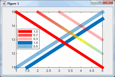
So, for example, let's modify the middle (30%-transparent) red line to something more colorful:
>> cd=uint8 ( [ 255,200,250,50,0; 0,50,250,150,200; 0,0,0,100,150; 179,150,200,70,50 ] ) cd = 255 200 250 50 0 0 50 250 150 200 0 0 0 100 150 179 150 200 70 50 >> set (h2b.Edge, 'ColorBinding','interpolated', 'ColorData',cd )
>> cd=uint8([255,200,250,50,0; 0,50,250,150,200; 0,0,0,100,150; 179,150,200,70,50]) cd = 255 200 250 50 0 0 50 250 150 200 0 0 0 100 150 179 150 200 70 50 >> set(h2b.Edge, 'ColorBinding','interpolated', 'ColorData',cd)

As you can see, we can interpolate not only the colors, but also the transparency along the line.
Note: We need to update all the relevant properties together, in a single set() update, otherwise we'd get warning messages about incompatibilities between the property values. For example:
>> h2b.Edge.ColorBinding = 'interpolated'; Warning: Error creating or updating LineStrip Error in value of property ColorData Array is wrong shape or size (Type "warning off MATLAB:gui:array:InvalidArrayShape" to suppress this warning.)
Markers
Note how the markers are clearly seen in the transparent lines but not the opaque ones. This is because the markers have the same color as the lines in today's example. Since the lines are wide, the markers are surrounded by pixels of the same color. Therefore, the markers are only visible when the surrounding pixels are less opaque (i.e., lighter).
As a related customization, we can control whether the markers appear "on top of" (in front of) the line or "beneath" it by updating the Edge.Layer property from 'middle' to 'front' (there is also 'back', but I guess you won't typically use it). This is important for transparent lines, since it controls the brightness of the markers: "on top" (in front) they appear brighter. As far as I know, this cannot be set separately for each marker – they are all updated together.
Of course, we could always update the line's fully-documented MarkerSize, MarkerFaceColor and MarkerEdgeColor properties, in addition to the undocumented customizations above.
Next week I will describe how we can customize plot line markers in ways that you never thought possible. So stay tuned 🙂
Leave a Reply
HTML tags such as <b> or <i> are accepted.Wrap code fragments inside <pre lang="matlab"> tags, like this:
<pre lang="matlab">I reserve the right to edit/delete comments (read the site policies).
a = magic(3);
disp(sum(a))
</pre>
Not all comments will be answered. You can always email me (altmany at gmail) for private consulting.
How to Draw a Line on a Png Matlab
Source: https://undocumentedmatlab.com/articles/plot-line-transparency-and-color-gradient
0 Response to "How to Draw a Line on a Png Matlab"
Post a Comment